
Molecular Foundations of PTFE Cable Film
Polytetrafluoroethylene (PTFE) exhibits extraordinary electrical insulation capabilities due to its fundamental chemical architecture. High-frequency radio signals require dielectric materials that do not store electrical charge or absorb signal energy. The molecular construction of PTFE cable film satisfies these demands through structural symmetry, strong atomic bonds, and engineered air void integration.
Non-Polar Molecular Symmetry
The high performance of PTFE stems from its fully symmetrical chemical structure. Long chains of carbon atoms form a central backbone, while fluorine atoms completely surround this core.
- Symmetrical Fluorine Shielding: The uniform arrangement of fluorine atoms around carbon creates a balanced shell that halts permanent electric dipole formation.
- Absence of Permanent Dipoles: Because no permanent dipoles exist, applied electric fields find no molecular charges to orient or polarize.
- Minimal Field Interaction: The structural balance renders the molecules virtually non-responsive to external electrical excitation, keeping polarizability and dielectric constant extremely low.
Even though individual C–F bonds possess polarity, the overall symmetry of the carbon backbone causes these dipole moments to neutralize one another. Consequently, the material exhibits a negligible dipole response. External electromagnetic fields pass through the dielectric layer without losing energy to molecular rotation or displacement.
Note on Dielectric Behavior: When alternating electric fields encounter non-polar molecules, the absence of net molecular dipoles prevents internal friction and thermal dissipation. This property stabilizes high-frequency RF transmission across a wide temperature spectrum.
Low Polarizability of Carbon-Fluorine Bonds
The chemical bond between carbon and fluorine is one of the strongest single bonds in organic chemistry. Fluorine holds its electrons tightly near its nucleus due to its high electronegativity. This intense atomic attraction restricts electron cloud movement when external electromagnetic forces interact with the material.
| Molecular Characteristic | Physical Mechanism | Effect on RF Signal |
|---|---|---|
| High Electronegativity | Fluorine tightly binds valence electrons | Prevents charge displacement |
| Small Ionic Radius | Short C-F bond length increases stability | Resists electric field deformation |
| Low Electronic Polarizability | Electron clouds remain rigid under high frequencies | Maintains extremely low relative permittivity ($\varepsilon_r \approx 2.1$) |
Because the electron clouds around the fluorine atoms resist distortion, the material stores minimal electrical potential energy during RF wave propagation. This rigid electronic configuration ensures exceptional resistance to dielectric breakdown while supporting rapid signal flow along the conductor.
Microporous Density Reduction in ePTFE
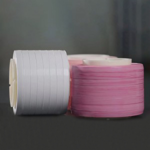
Expanding pure PTFE creates a microporous structure containing a network of nodes and fibrils. Advanced manufacturing processes produce ePTFE cable film, such as JINYOU ePTFE Cable Film, which incorporates microscopic air pockets directly into the insulation layer.
Pure PTFE (Density ≈ 2.15 g/cm³, εr ≈ 2.1)
  └─► Mechanical Expansion Process
        └─► ePTFE Film (Air Voids Included, Density < 1.0 g/cm³, εr ──► 1.3 - 1.7)
Air possesses a dielectric constant very close to ideal vacuum ($\varepsilon_r \approx 1.0$). By introducing controlled air voids, the expansion process lowers the overall density of the polymer matrix. Lower physical density directly translates to a reduced effective dielectric constant.
This engineered micro-porous geometry allows cable manufacturers to design thinner, lighter insulation layers. The reduced dielectric constant maximizes signal speed while dramatically lowering attenuation across complex coaxial cable assemblies.
How PTFE Cable Film Prevents RF Signal Loss
High-frequency radio signals lose energy as they travel along transmission lines. Dielectric materials inside coaxial cables absorb electromagnetic energy and release it as unwanted heat. Advanced insulation materials reduce these transmission losses, protecting signal strength across long distance runs.
Minimizing Dielectric Attenuation
Dielectric attenuation represents a primary source of signal loss at microwave and millimeter-wave frequencies. Cable insulation absorbs a portion of the electric field during alternating current cycles.
The dielectric loss tangent ($\tan \delta$ or $D_f$) quantifies the proportion of stored electromagnetic energy that converts into heat per alternating current cycle. A smaller loss tangent directly reduces dielectric heating and prevents attenuation, allowing high-frequency signals to propagate with minimal power dissipation.
| Parameter | Value/Range | Effect on High-Frequency Signal Energy |
|---|---|---|
| PTFE Dissipation Factor ($\tan \delta$) | 0.0002 – 0.0004 | Ensures exceptionally low energy dissipation as heat during AC cycles |
| Dielectric Performance | Exceptionally Low Loss | Preserves signal integrity in microwave and high-frequency cable applications |
The ultra-low dissipation factor of fluoropolymers keeps heat generation near zero. High-performance JINYOU ePTFE Cable Film combines low dielectric constant with exceptional dissipation factors, maintaining maximum power transfer across demanding RF assemblies.
Key Takeaway: Lowering the loss tangent reduces heat dissipation within the cable dielectric layer, preserving original signal power at high operating frequencies.
Maximizing Propagation Velocity
Relative permittivity ($\varepsilon_r$) dictates signal speed inside coaxial cables. Lower relative permittivity allows electromagnetic waves to travel closer to the speed of light in a vacuum ($c$). Engineers rely on ptfe cable film to achieve maximum propagation velocity in high-speed transmission lines.
| Transmission Metric | Lower VoP Standard | Higher VoP Standard | Net Performance Difference |
|---|---|---|---|
| Velocity of Propagation (VoP) | 66% speed of light | 85% speed of light | +19% faster propagation |
| One-Way Delay per 10 Meters | ~50.5 nanoseconds | ~39.2 nanoseconds | ~11.3 nanoseconds latency reduction |
Higher propagation velocity directly improves system responsiveness across sensitive RF equipment:
- Direct Latency Reduction: Boosting the velocity of propagation decreases the physical time required for an RF signal to travel along the length of a transmission line.
- System Synchronization: Minimizing propagation delay ensures proper timing across time-critical aerospace networks and digital interconnects.
- Phase Accuracy: In phased array radar and RF applications, lower cable delay reduces phase errors, while in differential data channels it prevents signal skew.
Expanding PTFE creates porous air pockets that drive relative permittivity down toward 1.3. This structural transformation maximizes speed and lowers processing latency for critical high-frequency devices.
Eliminating Phase Dispersion
Broadband RF signals contain multiple frequency components. Phase dispersion occurs when different frequencies travel at different phase velocities through a cable dielectric. Variable phase velocity distorts complex digital waveforms and analog signal profiles over time.
A flat dielectric constant profile across a wide frequency spectrum prevents dispersion. Expanded ptfe cable film delivers ultra-stable dielectric performance from low megahertz ranges through millimeter-wave bands.
Input Broadband RF Signal ──► [ Uniform Dielectric Constant ] ──► Distortion-Free Output Waveform
                                  (Stable Phase Velocity)
Uniform density throughout the insulating layer eliminates localized permittivity variations. Standard insulation materials alter their dielectric properties under changing thermal conditions, causing phase drift. Specialized expanded fluoropolymer structures maintain structural stability across high temperature swings, ensuring absolute phase stability in harsh operational environments.
Impedance and Capacitance in Cable Design
Precision coaxial cables demand exact alignment between physical dimensions and electrical properties. Managing impedance and capacitance ensures maximum power transfer across high-frequency RF interconnects.
Achieving Stable Characteristic Impedance
Characteristic impedance depends directly on conductor geometry and dielectric permittivity. Permittivity fluctuations cause localized impedance variations, triggering harmful signal reflections.
Z0 = (138 / √εr) * log10(D / d)
  ├── Z0: Characteristic Impedance
  ├── εr: Dielectric Constant
  └── D/d: Diameter Ratio of Outer to Inner Conductor
Engineers rely on ePTFE material to eliminate impedance drift along transmission lines. JINYOU ePTFE cable film provides exceptional structural uniformity across long cable lengths. Consistent material density prevents signal scattering and maintains steady wave impedance.
Key Insight: Uniform permittivity along the dielectric layer eliminates signal reflections, keeping voltage standing wave ratios (VSWR) at ideal values.
Reducing Inter-Conductor Capacitance
High inter-conductor capacitance stores excess electrical charge within the insulation. Stored charge slows down signal transitions and distorts dynamic RF waveforms.
- Lower Charge Storage: Microporous structures reduce relative permittivity down near air levels.
- Faster Response: Minimal capacitance enables rapid voltage transitions in digital RF channels.
- Reduced Energy Losses: Lower charge accumulation prevents reactive power loss in the cable matrix.
Using expanded ptfe cable film lowers total inter-conductor capacitance significantly. Cable designers create thinner insulation layers while preserving optimum electrical shielding and lower insertion loss.
Thermal Stability Across Frequency Bands
Temperature changes cause standard polymers to expand, altering physical dimensions and dielectric constants.
| Performance Metric | Standard Polymers | Advanced ePTFE Film |
|---|---|---|
| Thermal Expansion | High dimensional drift | Minimal structural change |
| Dielectric Drift | Shifts with temperature | Constant across wide range |
| Operational Limit | Low temperature ceiling | High thermal endurance |
Fluoropolymer film maintains stable physical dimensions and dielectric values across extreme operating environments. This thermal endurance protects high-frequency assemblies against phase shifts and impedance mismatch.
High-Frequency Applications for PTFE Cable Film
Advanced electronic systems require high-performance insulation to maintain signal purity in demanding operational environments. Expanded ptfe cable film supports high-frequency data transmission across critical aerospace, telecommunication, and defense installations.
Aerospace and Avionics Wiring
Spaceflight and satellite RF interconnects operate under extreme thermal cycles. System engineers choose expanded fluoropolymer insulation over standard polymers due to critical performance advantages:
- Thermal Stability: Maintains minimal phase fluctuations across temperature swings while keeping impedance variations below 3%.
- Superior Electrical Efficiency: Delivers ultra-low signal attenuation through a low dielectric constant.
- Mass Reduction: Cuts physical insulation weight by 30% to 60% compared to solid dielectrics.
- Outgassing Compliance: Prevents vacuum precipitation contamination on sensitive satellite optical instruments.
5G Telecommunications Infrastructure
Modern 5G infrastructure relies on millimeter-wave frequencies to deliver rapid data speeds. Base station antennas and massive MIMO systems demand low-loss interconnects to handle dense signal traffic. Utilizing high-porosity insulation minimizes insertion loss across high-density cell sites. Thin microporous wrapping tapes allow tight bend radii inside compact equipment cabinets without compromising shielding or electrical performance.
Radar and Microwave Test Assemblies
Phase stability indicates a cable’s ability to maintain a constant electrical length despite ambient thermal shifts. Because standard PTFE dielectrics undergo significant phase variations around room temperature (19°C to 23°C), even minor phase fluctuations can induce major distortions in radar beam pointing accuracy and pattern shape.
- Beamforming Dependence: Phased-array systems rely on exact phase adjustments across individual antenna feeds to direct signal beams accurately.
- Suppressed Phase Drift: Advanced ptfe cable film minimizes thermal hysteresis, protecting tracking accuracy in fluctuating environments.
A low dielectric constant in ptfe cable film forms the foundation for low-loss, high-speed RF signal transmission across microwave and millimeter-wave frequencies. Non-polar molecular structures and microporous designs resolve signal attenuation, phase distortion, and impedance drift within demanding operational environments. Optimized fluoropolymer insulation guarantees exceptional electrical reliability and long-term performance across next-generation high-frequency interconnect systems.
FAQ
What makes ePTFE cable film ideal for high-frequency RF transmission?
JINYOU ePTFE cable film provides a low dielectric constant near 1.3. This microscopic air-void structure minimizes signal loss and maximizes propagation velocity across high-frequency cables.
How does low relative permittivity prevent signal distortion?
Low relative permittivity minimizes inter-conductor capacitance and electrical energy storage. This reduction prevents insertion loss, stabilizes characteristic impedance, and eliminates phase dispersion in RF interconnects.
Why does expanded PTFE perform better than solid PTFE in coaxial cables?
Expanding PTFE introduces controlled air pockets into the polymer matrix. Because air has a dielectric constant near 1.0, ePTFE lowers overall density and reduces electrical attenuation.
See Also
Post time: Jul-22-2026